
- Home
- Products
- Mirrorless Z 30
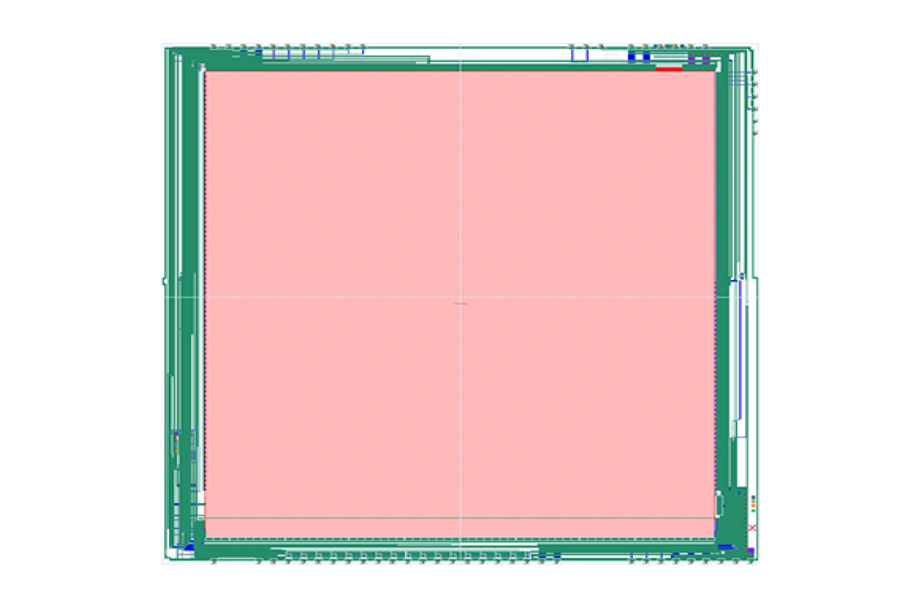
Mega-pixel 2K × 2K readout integrated circuit (ROIC) optimized for Indium Antimonide (InSb), Type-II strained-layer superlattice (T2SLS) and Quantum Well (QWIP) infrared detectors
FLIR ISC1902
The ISC1902 is a 2048 × 2048 format, 10-micron pitch device designed for P-on-N detectors with a direct injection input circuit. The ISC1902 is the big brother to the ISC1901 and supports all the same features with higher resolution. This includes single sample or sub-frame averaging for effective well fill of 3 to 19M electrons, respectively. The selectable settings allow user control of modes such as 2 × 2 binning, 8 or 16 output channels and additional reverse bias for QWIP detectors. Teledyne FLIR’s familiar user interface makes system integration straightforward.
ENHANCED THERMAL
PERFORMANCE
Greater resolution and sensitivity than common thermopile arrays.
AFFORDABLE MICRO THERMAL CAMERA WITH UNBEATABLE SWAP
Size, power, and lens options enable mobile devices, unattended sensors, and small electronics.
BUILT FOR PROFESSIONAL, LARGE-VOLUME INTEGRATORS
Develop with the industry’s leading thermal camera manufacturer to reduce risk, cost, and time to market.

GROW YOUR BUSINESS WITH LEPTON
Integrating Teledyne FLIR thermal camera modules is now easier with our library of how-to-videos, application notes, and our comprehensive support center with product drawings, datasheets, and more!

WHAT IS THERMAL BY FLIR?
Thermal by FLIR is a cooperative product development and marketing program that supports original equipment manufacturers (OEMs) and product innovators who use FLIR thermal imaging sensors in their products. With Thermal by FLIR, let us help you create the next market-changing innovation to grow your business.
8 Things to Consider When Choosing a Thermal Camera
Here are some things to keep in mind when determining how to choose the right thermal imager from Teledyne FLIR.

Camera Model
Selector
Sorting through more than 100+ models can be tricky. Try our “Camera Model Selector” to find the right solution.
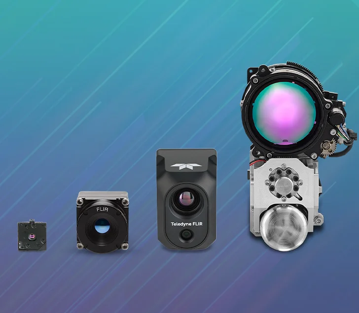
INNOVATE WITH THE INDUSTRY'S BEST CORES
With industry-leading reliability, performance, size, weight, and power, they are ideal for defense, commercial, and security applications.
Specifications
| PARAMETERS | DESCRIPTION |
|---|---|
| Thermal Imaging Detector | Uncooled microbolometer |
| Pixel Size | 17 µm |
| Frame Rate Options | 8.6 Hz (commercial application exportable) |
| Thermal Spectral Range | Longwave infrared, 8 µm to 14 µm |
| Scene Temperature Range | High Gain Mode: -10 °C to 140 °C (14 °F to 284 °F) Low Gain Mode: -10 °C to +450 °C (14 °F to 842 °F) |
| Temperature Accuracy | High gain: Greater of +/- 5°C (41 °F) or 5% (typical) Low gain: Greater of +/- 10°C (50 °F) or 10% (typical) |
Performance
| Scene Temperature Range | High Gain Mode: -10 °C to 140 °C (14 °F to 284 °F) Low Gain Mode: -10 °C to +450 °C (14 °F to 842 °F) | Thermal Spectral Range | Longwave infrared, 8 µm to 14 µm |
Radiometry
| Temperature Accuracy | High gain: Greater of +/- 5°C (41 °F) or 5% (typical) Low gain: Greater of +/- 10°C (50 °F) or 10% (typical) |
Imaging & Optical
| Array format | 80 × 60, progressive scan |
| FOV – Diagonal | 63.5° |
| FOV – Horizontal | 50° (nominal) |
| Frame Rate Options | 8.6 Hz (commercial application exportable) |
| Image Optimization | Factory configured and fully automated |
| Non-Uniformity Correction (NUC) | Integrated Shutter |
| Thermal Imaging Detector | Uncooled microbolometer |
| Thermal Sensitivity | ≶ 50 mK (0.050° C) |
| Video Data Interface | Video over SPI |
Connections & Communications
| Output Format | User-selectable 14-bit, 8-bit (AGC applied), or 24-bit RGB (AGC and colorization applied) |
Electrical
| Control Port | CCI (I2C-like), CMOS IO Voltage Levels |
| Input Clock | 25-MHz nominal, CMOS IO Voltage Levels |
| Input Voltage | 2.8 V, 1.2 V and 2.5 V to 3.1 V IO |
| Power Dissipation | 150 mW (operating), 650 mW (during shutter event), 4 mW (standby) |
Mechanical
| Mechanical Interface | 32–pin socket interface to standard Molex® socket |
| Package Dimensions – Socket Version (w x l x h) | 11.8 x 12.7 x 7.2 mm |
| Weight | 0.9 grams (without socket) |
Environmental & Approvals
| Non-Operating Temperature Range | -40 °C to +80 °C (14 °F to 176 °F) |
| Optimum Temperature Range | -10°C to +80°C (-40 °F to 176 °F) |
| Shock | 1500 G @ 0.4 ms |
| Solar protection | Integrated |
| Temperature Compensation | Automatic. Output image independent of camera temperature. |
Export Designations
| ECCN Code | 6A993.A |
Related Content
Accessories
Media gallery


EOC Tech’s Thermal Imaging IP Camera | Mobile World Congress 2024
RealWear Navigator Z1|Mobile World Congress 24
Blackview BL9000 Pro|Mobile World Congress 2024


